No communication with U0151 Airbag Module
U0151 Lost Communication with Airbag Control Module: Comprehensive Guide When the U0151 diagnostic trouble code (DTC) appears in your vehicle, it indicates a Lost Communication with the Airbag Control Module. This critical issue directly impacts the functionality of your vehicle’s Supplemental Restraint System (SRS), potentially compromising occupant safety. Addressing this...

- 1. U0151 Lost Communication with Airbag Control Module: Comprehensive Guide
- 1.1. What Does U0151 Lost Communication with Airbag Module Mean?
- 1.2. The CAN Bus and the Airbag Module
- 2. Common Symptoms of DTC U0151
- 3. Causes of U0151 Lost Communication with Airbag Module
- 3.1. 1. Wiring Harness or Connector Failures
- 3.2. 2. Defective Airbag Control Module (SRS Module)
- 3.3. 3. Low Battery Voltage or Power Supply Issues
- 3.4. 4. CAN Bus Network Failures
- 3.5. 5. Blown Fuses
- 3.6. 6. Faults in Other Network Modules
- 3.7. Common Causes and Diagnostic Solutions Summary
- 4. Diagnostic Steps for DTC U0151
- 4.1. Step 1: Scan for System Codes
- 4.2. Step 2: Comprehensive Visual Inspection
- 4.3. Step 3: Battery and Charging System Evaluation
- 4.4. Step 4: CAN Bus Circuit Impedance Testing
- 4.5. Step 5: Power and Ground Circuit Verifications
- 4.6. Step 6: Module Response Isolation
- 5. Repair and Resolution Options
- 6. Preventive Measures and Maintenance
- 7. Frequently Asked Questions (FAQ)
- 7.1. Summary
U0151 Lost Communication with Airbag Control Module: Comprehensive Guide
When the U0151 diagnostic trouble code (DTC) appears in your vehicle, it indicates a Lost Communication with the Airbag Control Module. This critical issue directly impacts the functionality of your vehicle’s Supplemental Restraint System (SRS), potentially compromising occupant safety. Addressing this error promptly is vital.
The code signifies that the airbag control module cannot communicate with other control units via the network. Consequently, the airbags may fail to deploy during a collision. Below you will find in-depth information regarding the causes, symptoms, diagnostic methods, and effective repair solutions for this fault, alongside detailed tables and a Frequently Asked Questions (FAQ) section.
What Does U0151 Lost Communication with Airbag Module Mean?
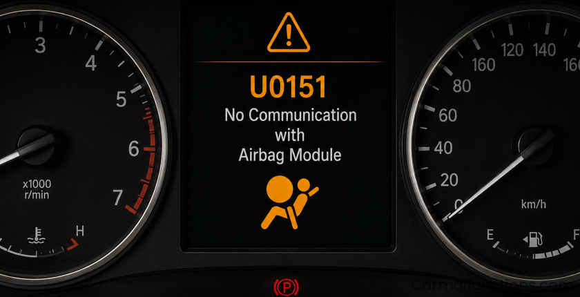
The U0151 fault code indicates a communication interruption between the airbag control module—alternatively referred to as the Airbag Control Cluster Module (ACCM) or SRS Module—and the vehicle’s Controller Area Network (CAN) bus. The CAN bus is a specialized network that allows different Electronic Control Units (ECUs) within the vehicle to exchange data seamlessly. The presence of this code demonstrates that the airbag safety framework is compromised, meaning the airbags might not deploy during an accident, which drastically elevates the risk of severe injury.
The CAN Bus and the Airbag Module
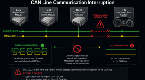
The CAN bus network acts as the central nervous system in modern vehicles. Crucial modules, including the Engine Control Module (ECM), Transmission Control Module (TCM), and the Airbag Module, exchange real-time telemetry over this data highway.
The airbag module continuously monitors data received from impact and crash sensors. When a collision profile is identified, it commands the immediate deployment of airbags and seatbelt pretensioners. A U0151 error points to a disruption in this critical data link, often stemming from a breakdown in the module’s power supply, grounding circuit, or localized CAN bus wiring.
Common Symptoms of DTC U0151
The U0151 fault code generally manifests through distinct warning indicators. Recognizing these symptoms helps gauge the severity of the issue:
-
Airbag / SRS Warning Light: The airbag or SRS warning light illuminates permanently on the dashboard. This is the most common and immediate indicator.
-
Check Engine Light (MIL): In specific vehicle architectures, safety system communication failures can trigger the Malfunction Indicator Lamp (MIL).
-
Concurrent Communication DTCs: Additional communication-related trouble codes (typically starting with “U”) may be stored in neighboring modules, signaling a broader network or CAN bus disruption.
-
No-Start Condition: While rare, certain vehicle manufacturers configure security or network gateways to prevent the vehicle from starting if critical modules like the SRS unit are missing from the network.
-
Stored Diagnostic Code: The U0151 code will be present and read out during an OBD-II diagnostic scan.

Causes of U0151 Lost Communication with Airbag Module
Several distinct factors can trigger a U0151 communication fault. Isolating these factors is necessary for accurate diagnostics and repairs:
1. Wiring Harness or Connector Failures
The wiring harness and specialized connectors supply both stable operating power and differential data lines to the airbag module. Physical degradation breaks this link:
-
Chafed or Broken Wires: Heavy vibrations, mechanical rubbing, or rodent damage can sever critical wires.
-
Corrosion: Moisture intrusion oxidizes connector pins, leading to high electrical resistance or open circuits.
-
Loose Connector Fitment: Locking tabs can degrade over time, leading to loose connections and intermittent communication dropouts.
-
Short Circuits: Insulation breakdown can cause data lines to short to ground or power.
2. Defective Airbag Control Module (SRS Module)
Internal hardware degradation within the SRS module itself will cause it to go offline. Internal microprocessors or surface-mount components can fail due to historical impact shock, localized heat cycles, or fluid ingress. Once an internal component fails, the module fails its initialization and drops off the CAN bus.
3. Low Battery Voltage or Power Supply Issues
Sensitive electronic control modules require clean, stable voltage to broadcast data. Low battery voltage or excessive voltage drops during starting can prevent the airbag module from booting up fast enough, triggering a network timeout. Loose or corroded battery terminals compound this issue.
4. CAN Bus Network Failures
Because the CAN bus is the shared network backbone, localized faults along the communication lines can isolate the SRS module entirely:
-
Open Circuits: A break anywhere along the CAN High or CAN Low lines.
-
Short Circuits: CAN lines shorted together, or shorted directly to chassis ground or 12V power.
-
Impedance / Terminating Resistor Faults: The CAN bus relies on specific terminating resistors (typically two 120-ohm resistors in parallel yielding a total network resistance of 60 ohms) to prevent signal reflection. A fault here garbles communication.
5. Blown Fuses
Airbag modules rely on dedicated fuses for unswitched and ignition-switched power. A blown fuse cuts off all power to the unit. Without power, the module cannot communicate, making checking the fuse box a fundamental diagnostic step.
6. Faults in Other Network Modules
In a linked network topology, a failing module elsewhere on the bus (such as a malfunctioning Body Control Module – BCM) can flood the CAN network with erratic data or short out the communication lines, indirectly cutting off communication to the airbag module.
Common Causes and Diagnostic Solutions Summary
| Potential Cause | Description | Diagnostic / Repair Solution |
| Wiring Harness/Connector Damage | Chafed, broken, corroded, or unsecured wiring and pin connectors. | Visual inspection, circuit repair, or harness replacement. |
| Airbag Module Internal Failure | Degradation or terminal damage to the module’s internal electronics. | Replace the SRS module followed by VIN programming. |
| Low Battery System Voltage | Insufficient system voltage prevents proper module initialization. | Load test the battery; recharge or replace as needed. |
| CAN Bus Infrastructure Issues | Open circuits, shorts, or terminating resistor faults on CAN High/Low lines. | Network isolation testing, circuit tracing, or wire repair. |
| Blown Power Fuse | Complete loss of supply voltage due to a compromised safety fuse. | Inspect the fuse panel; replace with an identical amperage fuse. |
Diagnostic Steps for DTC U0151
Diagnosing a U0151 code requires a highly systematic approach. Always exercise extreme caution: SRS frameworks handle pyrotechnic deployment charges. Unprofessional testing or incorrect equipment usage can trigger accidental deployment, causing severe injury.
Step 1: Scan for System Codes
Connect an advanced OBD-II diagnostic scanner to evaluate the vehicle’s network layout. Check if U0151 stands alone or if it is accompanied by other network communication codes (e.g., U-codes from the BCM or ECM). A multi-module communication failure points to a centralized network network issue rather than an isolated module problem.
Step 2: Comprehensive Visual Inspection
Locate the airbag control module, which is typically mounted centrally near the vehicle floorboards under the lower center console stack or beneath the front seats. Inspect the following:
-
Harness Integrity: Check for signs of wire pinching, exposure, or modifications.
-
Connectors: Unplug the connector (with the battery disconnected) and look for bent pins, moisture, or green copper oxidation.
-
Power Fuses: Use a test light or multimeter to check the continuity of all fuses tied to the SRS, Airbag, or Passenger Occupant Detection systems using the vehicle’s manual.
-
Physical Module Condition: Look for signs of outer casing distortion, rust, water stains, or a distinct electrical burning odor.
Step 3: Battery and Charging System Evaluation
Measure the static and cranking voltage of the vehicle battery using a digital multimeter. The battery must be structurally sound and fully charged. Verify that the alternator’s charging output is stable and falls within normal operating parameters.
Step 4: CAN Bus Circuit Impedance Testing
With the vehicle battery completely disconnected to protect internal electronics, measure the resistance between the CAN High and CAN Low pins at the Data Link Connector (DLC / OBD port).
-
A healthy network should register approximately 60 ohms.
-
Reading 120 ohms indicates an open circuit in one of the network branches or a failed terminating resistor.
-
A reading near 0 ohms indicates a direct short between the data lines.
Step 5: Power and Ground Circuit Verifications
Reconnect the battery and turn the ignition to the “ON” position. Using a digital multimeter, check for a solid 12V supply at the primary power input pin on the airbag module’s harness connector. Next, perform a voltage drop or resistance test on the ground pin to guarantee a direct, low-resistance connection to the chassis.
Step 6: Module Response Isolation
Use a bi-directional scan tool to attempt a direct module ping or communication test with the SRS unit. If the module receives adequate power, has a solid ground, and sits on a healthy CAN line but still yields no response, the module itself is likely completely non-functional.
Repair and Resolution Options
Once your diagnostics isolate the source of the breakdown, proceed with the corresponding repair path:
-
Wiring and Connector Reconstruction: Repair compromised circuits by splicing or using specialized pin-repair kits. Always solder and heat-shrink automotive data lines to maintain critical resistance metrics. Clean oxidized pins with electronic contact cleaner.
-
Fuse Replacement: Replace a blown fuse with a matching amperage rating. If the new fuse blows immediately, do not upsize it; trace the circuit to locate and resolve the underlying short circuit.
-
Airbag Control Module Replacement: If the module is confirmed dead, it must be replaced. Replacement units typically require vehicle-specific flashing, VIN matching, and occupancy sensor calibration using dedicated factory software. Disconnect the battery for at least 15 minutes before unbolting an old module.
-
CAN Bus Infrastructure Correction: Trace out the network topology to find shorts or broken splices in the CAN network. This delicate process may require replacing targeted sections of twisted-pair communication wiring.
-
Power Supply Restoration: Clean corroded battery terminals, secure loose ground straps, and replace defective batteries or failing alternators to stabilize system voltage.
Preventive Measures and Maintenance
Maximize the reliability of your vehicle’s safety electronics with these steps:
-
Routine Inspections: Request a full module scan during regular dealership servicing to catch intermittent communication codes before they trigger a hard fault.
-
Protect Cabin Harnesses: Avoid crimping under-seat or center-console wiring harnesses when installing aftermarket accessories, detailing the interior, or modifying brackets.
-
Prevent Moisture Ingress: Keep the interior floorboards dry. Address clogged sunroof drains, leaking door seals, or heater core leaks immediately, as pooling water quickly floods the SRS module’s floorboard location.
-
Post-Collision Audits: Always have the complete safety framework inspected professionally following any minor collision or suspension impact.
Frequently Asked Questions (FAQ)
How critical is the U0151 diagnostic code?
The U0151 code is exceptionally critical. Because it denotes a total communication failure with the airbag module, your vehicle’s supplemental restraint system is disabled. Airbags will not deploy in a crash, leaving occupants unprotected.
Can I continue driving with a U0151 code active?
Driving with an active U0151 code is highly discouraged. While the vehicle may drive normally, you have no functional airbag protection. You should drive directly to a certified repair facility to resolve the issue safely.
Where is the airbag control module typically located?
While layout specifics vary by vehicle manufacturer, the SRS module is almost always securely bolted directly to the structural floor pan of the vehicle, hidden underneath the lower dashboard center console stack or beneath the driver/passenger front seats.
Can I replace a faulty airbag module on my own?
DIY replacement is not recommended. Beyond the physical risk of accidental deployment due to static electricity or incorrect handling, modern SRS modules must be programmed with specialized factory equipment to align with your vehicle’s VIN and configuration parameters.
How do I permanently clear the U0151 code?
The U0151 code cannot simply be erased via a basic scan tool while the underlying fault exists; the system re-evaluates communication lines constantly. Once the bad wiring, blown fuse, or defective module is repaired, the code can be cleared, and the SRS dashboard light will extinguish.
Summary
The U0151 Lost Communication with Airbag Module error is a definitive safety warning that requires immediate technical resolution. Ignoring this code puts everyone in the vehicle at risk. Isolating the issue requires checking fuses, inspecting connectors for corrosion, verifying battery output, and measuring CAN bus network resistance. Due to the high-stakes nature of supplemental restraint components, do not hesitate to leverage professional automotive expertise to ensure your system is reprogrammed, calibrated, and fully functional.